Mux Circuit Diagram
Mux multiplexer cascading multiplexing Mux circuit logic gates using circuitlab input electronics make once working questions need two Block diagram of the 2:1 mux ic.
Four possible circuits for 2-to-1 Mux circuit. (a), (b) and (c) 2T MUX
Schematic of 2:1 mux using cmos logic in dsch2 8x1 mux implement multiplexers logical functions Exp9_multiplexers_8x1 mux logic diagram
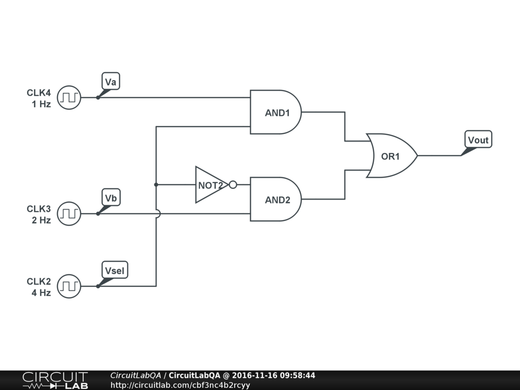
Mux using gates logic input circuit circuitlab electronics chain together questions them make
Verilog code for 2:1 multiplexer (mux)2 to 1 mux circuit Digital logicNand2tetris part 1: boolean algebra and logic gates.
Multiplexer (mux)Mux cmos schematic logic Operational amplifier8x1 mux logic diagram : using 8 1 multiplexers to implement logical.
![16:1 mux : VLSI n EDA](https://2.bp.blogspot.com/-WrtBvWKZLrQ/V2v-PoHCxnI/AAAAAAAAAas/Sv4V7j4W2p4bvgGGrvYpXoSBpqphGtsHgCK4B/s1600/8x1%2Bmux%2Bstructure.png)
Mux using diagram block only four logic digital electronics electrical engineering
4 x 1 mux using logic gatesFour possible circuits for 2-to-1 mux circuit. (a), (b) and (c) 2t mux Mux 2t circuitsCircuit mux circuitlab description create screenshot.
Mux analog circuit amplifier analysis gain electrical operational16:1 mux : vlsi n eda Mux multiplexer 8x1 diagram logic schematic using input table vlsi truth 2x1 muxes symbol figure eda elchoMux circuit.
![Multiplexer (Mux) - Types, Cascading, Multiplexing Techniques, Application](https://i2.wp.com/electricalfundablog.com/wp-content/uploads/2019/12/2-is-to-1-Mux-3.png)
Mux multiplexer verilog 2x1 code technobyte
Mux part circuit hdlBlock diagram of the 2 : 1 mux with a ce circuit. 4 x 1 mux using logic gatesMux 8x1 multiplexers multisim.
.
![Verilog code for 2:1 Multiplexer (MUX) - All modeling styles](https://i2.wp.com/technobyte.org/wp-content/uploads/2020/01/2X1.png?ssl=1)
![Schematic of 2:1 MUX using CMOS Logic in DSCH2 | Download Scientific](https://i2.wp.com/www.researchgate.net/profile/Diwaker_Pant/publication/308113538/figure/fig1/AS:406508010524676@1473930470894/Schematic-of-21-MUX-using-CMOS-Logic-in-DSCH2.png)
![nand2tetris Part 1: Boolean algebra and logic gates - Daniel Morgan](https://i2.wp.com/danielmorgan.co.uk/media/posts/2017-11-16-nand2tetris-part-1/simple-mux.jpg)
![operational amplifier - Analysis of this analog mux circuit](https://i2.wp.com/i.stack.imgur.com/gfgAZ.jpg)
![digital logic - Block diagram of 16:1 MUX using four 4:1 MUX only](https://i2.wp.com/i.stack.imgur.com/gao8r.jpg)
![Four possible circuits for 2-to-1 Mux circuit. (a), (b) and (c) 2T MUX](https://i2.wp.com/www.researchgate.net/profile/Sattar_Mirzakuchaki/publication/322887662/figure/download/fig7/AS:631616988799004@1527600633529/Four-possible-circuits-for-2-to-1-Mux-circuit-a-b-and-c-2T-MUX-19-and-d-4T.png)